Disclaimer: I am not responsible for any damage done to your Atari. This mod is designed to allow you to pause your system. The mod will work if performed correctly to a fully functioning Atari. Perform at your own risk.
Tools You Will Need
Philips Screwdriver
Soldering Iron and Solder
De-soldering Tool (De-soldering Iron, Bubble, Vacuum, or Braid)
Wire Cutters/Strippers
Needle Nose Pliers
Drill with 1/4″ bit
Razor Blade
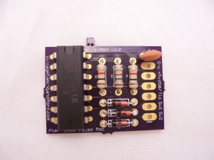
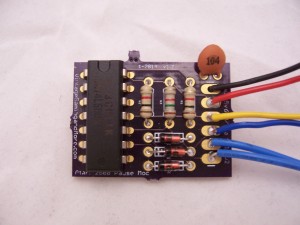
The first step is to assemble the mod kit. The components are all marked on the PCB, and you can also follow on the picture below. Make sure you put the 1k resistors on the outside and the 1.5k in the middle. The 1.5k will have a green stripe on it. The resistors and the ceramic disc capacitor can go in either direction. The 3 diodes and the 14 pin IC have to go in a certain way so make sure you follow the notches on the PCB and the picture below. Once you finish soldering all the components clip the excess leads off the bottom and you are done with the components.
Next you attach the wires to the mod kit. The holes in the circuit board are labeled for the wires. In order from top to bottom the color is Black for GND, Red for +5v (Vcc), Yellow for 6507, and blue for TIA. The other two long wires should go to Sw 1 and 2, they are for the switch. The color does not matter, so use whatever is included in the kit with Sw 1 and 2. Use the wire strippers to take off about 1/4″ and solder the wires into the mod board. Then solder the other end of the blue wires to the switch. One wire should go to the middle pole, and the other to the top or bottom. It does not matter which one goes where for the switch. Now the mod kit is ready to go.
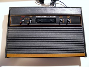
Next you need to open up your Atari. Turn the Atari over and remove the 4 screws. Set them aside for later. Remove the main board out of the console by disconnecting the RF cable. shown below. Take off the black foam covers on the switches and set them aside for later. Take the foil tape off the switches and you can try to save that as well but it isn’t a big deal if it rips off.
Using the need nose pliers, bend up the 4 tabs around the metal case. Remove the metal casing (top and bottom) and set it aside for later. You should now have the main board ready to be modified.
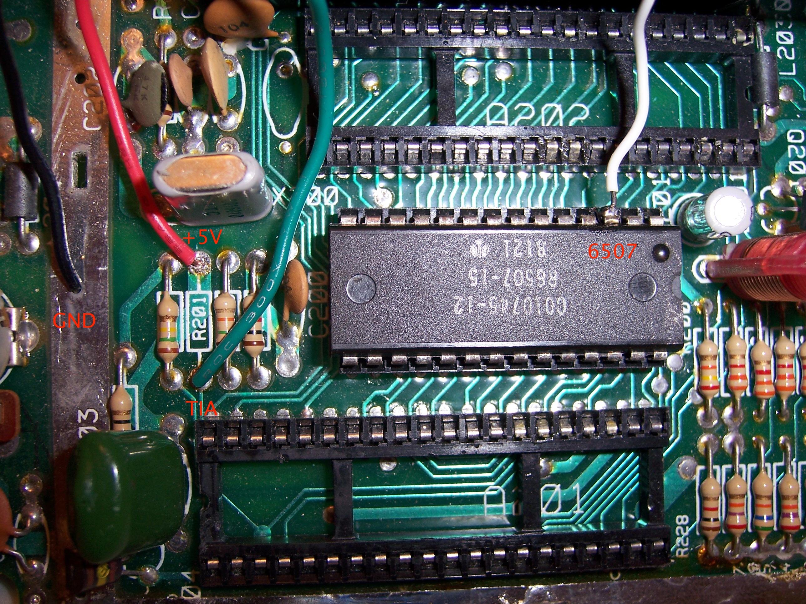
There are two modifications which must be made to the main board. First, you need to cut a trace with the razor blade, then you must remove a resistor (R201). The resistor is 4.7K (Yellow-Purple-Red). It’s location will slightly vary depending on what 4 switch version you have. Two different locations are pictured below, but it will always be in that general area. You can remove the resistor by de-soldering or cutting it. If you cut it be sure to use your de-soldering tool to clear both holes on the top and bottom as you will be using them for attaching wires.
Now this is the tricky part so be careful. There is a trace that needs to be cut with a razor blade that is marked with the small circle in the above pictures. You can cut anywhere along that trace you like. Be sure not to damage other traces. This will sever the connection between pin 3 of the TIA chip and pin 3 of the 6507 chip. When you are finished it’s a good idea to test for continuity between pin 3 of the two chips and make sure the trace has been severed. The picture below is what it looks like when finished.
Next it is time to connect the wires. The Black GND wire goes to the nearest hole on the metal strip where the casing was. The Red +5v goes to the top hole of R201. The Blue TIA goes to the bottom hole of R201. The Yellow 6507 wire goes to pin 3 of the 6507 IC. This is the most difficult to solder. The best way is to put some solder on the pin before you attach the wire. Then re-melt the solder and attach the wire. Be careful not to bridge the connection with the pins next to it and you don’t want to leave your soldering iron touching the pin for too long so you don’t risk damaging the chip.
Now you should test the Atari to make sure everything is working correctly. Attach the power and RF cable and fire it up. If the pause switch is on you will get a blank screen when powering on the system, so if you are not getting a picture try flipping the switch. If it still doesn’t work then check all of your connections and make sure they are correct. If it is hooked up correctly you should be able to pause your Atari (When paused the Atari will display random color or black output like the picture below, this is normal).
Now you are done with the main board. Use the double sided tape and attach the mod to the top of one of the IC chips. Then put the metal cover back on and make sure all the wires are tucked inside and don’t come loose in the process. The blue wires for the switch should be coming out of the left side of the metal casing. You can also drill a hole in the casing to feed the wires through if you like. Be sure to bend the metal tabs so the casing holds in place.
Now drill a 1/4″ hole for the toggle switch in the case. The location is pretty much based on your own preference, just make sure the blue wires are long enough and reach where the hole is. Remove the nut and washer and push the threaded part through the hole. Slip on the washer and then the nut and make sure it is tight enough so the switch doesn’t move around.
Replace the foam dust covers and foil strips for the switches. Feed the RF cable back through the bottom cover and then put the board back in the case and replace the top cover. Make sure everything fits and test the pause switch one more time before you put the screws back in. After that fire up a game and feel free to pause it whenever and get yourself a cold drink, you’ve earned it 🙂 Then leave me a comment and let me know how it went….
")