Disclaimer: I am not responsible for any damage done to your Atari. This mod is designed to permanently remove the RF output. The mod will work if performed correctly to a fully functioning Atari. Perform at your own risk.
Turn the Atari over and remove the 5 screws. There are 3 tabs, one on either end and one in the middle. Use a flat headed screwdriver or some similar tool to bend the tabs like in the picture so you can take the top cover off. If the tabs break it is not a problem as they can be a pain to get off. You don’t really need them because the screws hold it together. Now take the main board out of the bottom case by pushing out two more tabs on the inside.
Turn the main board over and using the needle nose pliers, bend up straighten the tabs around the metal cover. Remove the bottom metal cover and throw it away. Underneath it are more tabs to straighten. After that you can remove the top metal covers and throw them away.
On the right hand side of the board toward the bottom you need to remove some components. First you need to remove a Transistor (Q4) by cutting all three leads. Then remove a resistor (R56) by cutting both ends. You can throw both of them away. Then you need to use your de-soldering tool and remove the solder in the top hole of R56 and the hole furthest right of Q4 as in the picture on the right. You will be connecting wires in those holes in later steps.
Now you need to remove a capacitor (C33) and another resistor (R17). These components are just above the other ones you removed, where the smaller metal case was. Then use your de-soldering tool and open up the hole in the top right hand corner of the lower 40 pin IC(A3) near the center of the board. The label A3 is right next to the hole. If you are having trouble de-soldering any of these holes it is not a big deal as you can always heat the solder in the holes and then push the wires through instead.
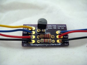
Now it’s time to assemble the circuit board. Just follow the picture below and solder in the transistor, 2.2k Resistor (Red-Red-Red), and 3.3k Resistor (Orange-Orange-Red). The components are labeled on the circuit board so it should be pretty easy to see where they go.
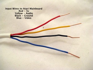
You should have two pieces of 4 conductor wire. First, strip off the white sheathing. You can save about an inch of it to help group the wires together if you like. Next, throw out one of the yellow wires. Now you should have two groups of wires. A group of 3 output wires (Red, Black, and Blue), and a group of 4 input wires (Red, Black, Blue, and Yellow). With the new wire I use, Blue replaces Green and Yellow replaces White in the other pictures. The group of 4 wires are the input wires that go to the main board. Strip about 1/2″ off of both ends of the input wires and attach them to the mod kit. Black is the GND, Red is +5v, Blue is Video, and Yellow is Audio.
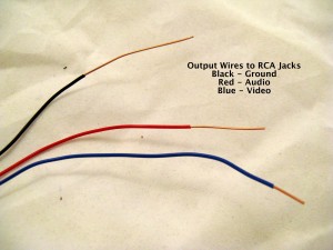
The group of 3 wires are out wires that attach to the RCA jacks. The output wires should be stripped to different lengths as in the picture. About 1/2″ for Blue, 1″ for Red, and 2″ for Black. On the output side of the mod kit, Black is for GND, Red for Audio, and Blue for Video.
Attach the input wires to the main board like in the picture and solder them in from underneath. The black wire goes into the metal strip around the board, the Red goes into the hole from Q4, the Blue into the top of R56, and the Yellow into the hole by A3. After this the main board is done.
Now you are going to drill holes for the RCA jacks. You need to be extremely careful as the Jr. case can be notoriously brittle and there isn’t much room to work with. Take the top half of the case and put a piece of masking tape on the right side. Mark the places where you want to drill holes by using a ruler and marker. Place them 1/2″ apart and then drill 1/8” pilot holes on the dots. Then use the 1/4” drill bits on the holes to make them ready for the RCA jacks.
Attach the RCA jacks by mounting them into the case with the ground ring and nut on the inside. Make sure they are tight. Have the ground ring holes be at or near he top and bend them down to make soldering easier. Take the Black output wire with the longest amount of bare wire and solder it to all three ground rings like in the picture below. Take the Red wire and solder it to the Red and White jacks. Take the Blue wire and solder it to the yellow jack.
Now you are ready to put the board into the case. But first you need to adjust the color potentiometer on the bottom left of the board. Plug in the RCA cables and put in a game with nice bright colors that you are familiar with, something like Frogger or Pitfall. Adjust the pot so the colors are just right.
Now unplug everything and put the board back in the bottom case. Then you need to attach the plastic strip for the select and reset switches.Then peel off the bottom of the double sided tape and stick it toward the lower right corner of the top cover. Now carefully put the top cover back on, making sure the mod circuit board and wires fit and the plastic strip doesn’t get disconnected. Now turn the console over and put the screws back in and you are ready to play your Atari with composite video! Please leave a comment below and let me know how it works!
8 thoughts on “Installation Guide – Jr.”
I bought the mod a couple months ago, but didn’t get around to installing till today. Works great! I’ve set it up on my HD set and also plugged in my Harmony cart. Thanks for this!
I am so pleased with the results that was given on my Australian PAL Atari 2600 JR. Clean clear Video with teriffic colours, The Sound quality is absolutely outstanding.
Works great! I am not experienced at all with a soldering tool but the instructions were helpful and I got the job done. Wasn’t really sure what to do with that small piece of double-sided tape… Other than that 100% satisfaction thank you!
Thanks for the product and the tutorial. It works well in my 2600 Jr. (Short rainbow). Playing on an HDTV is a nice change of pace from the 13″ tube tv that was used prior to the installation.
I’d also like to note that my 2600 had A LOT of “snow” in the image before installing the video mod. There is absolutely none after the installation.
Great product!
Worked very well, thanks.
I bought the mod and started it (fitted the rca sockets etc) about 5 years ago, but finally got around to finishing it today. Had trouble getting it to work, the Atari would only work intermittently, but re-read the instructions and somehow I had skipped the step where you have to remove the C33 and R17 components. Snipped those and it solved the problem. Works great!
Works, great. Thanks
I ordered received the mod a few days ago and just installed it. It works great. It looks so much better on my TV. The static is gone. It was easy enough to do and I have never soldered anything prior to this.


I bought the mod a couple months ago, but didn’t get around to installing till today. Works great! I’ve set it up on my HD set and also plugged in my Harmony cart. Thanks for this!
I am so pleased with the results that was given on my Australian PAL Atari 2600 JR. Clean clear Video with teriffic colours, The Sound quality is absolutely outstanding.
Here’s a photo to show the great quality on my AWA HDTV
http://i1239.photobucket.com/albums/ff505/MrJRussell87/IMG_0735.jpg
Works great! I am not experienced at all with a soldering tool but the instructions were helpful and I got the job done. Wasn’t really sure what to do with that small piece of double-sided tape… Other than that 100% satisfaction thank you!
Thanks for the product and the tutorial. It works well in my 2600 Jr. (Short rainbow). Playing on an HDTV is a nice change of pace from the 13″ tube tv that was used prior to the installation.
I’d also like to note that my 2600 had A LOT of “snow” in the image before installing the video mod. There is absolutely none after the installation.
Great product!
Worked very well, thanks.
I bought the mod and started it (fitted the rca sockets etc) about 5 years ago, but finally got around to finishing it today. Had trouble getting it to work, the Atari would only work intermittently, but re-read the instructions and somehow I had skipped the step where you have to remove the C33 and R17 components. Snipped those and it solved the problem. Works great!
Works, great. Thanks
I ordered received the mod a few days ago and just installed it. It works great. It looks so much better on my TV. The static is gone. It was easy enough to do and I have never soldered anything prior to this.